
When designing electrical and electronic appliances, engineers must assess the airflow needed to dissipate heat effectively. To avoid overheating, the required airflow depends on the system's power consumption, ensuring sufficient heat removal. Insufficient cooling can reduce the system's lifespan, negatively impacting sales and pricing due to shorter operational longevity than user expectations.
To choose the appropriate heat dissipation device, consider the following key objectives:
Here are three essential steps for selecting the right fan or Blower to meet these objectives:
Step 1: Total Cooling Requirements
The first step is to understand three critical factors to determine total cooling needs:
Meeting total cooling requirements is crucial for efficient system operation. An optimized system ensures that all components perform optimally, enhancing both performance and service life.
To select the appropriate fan motor, the following methods can be used:
The airflow volume needed to cool the equipment can be determined if the internal heat dissipation and the maximum allowable temperature rise are known.
The fundamental heat transfer equation is:
H = Cp × W × △T
Where:
We can express W as:
W = CFM × D, where D represents the air density.
Substituting this into the equation gives:
Q(CFM) = Q / (Cp × D × △T)
By applying the appropriate conversion factors and using the specific heat and density of sea-level air, the following heat dissipation equation is derived:
CFM = 3160 × KW / △℉
This results in the following equations:
Q(CFM) = 3.16 × P / △℉ = 1.76 × P / △Tc
Q(M³/Min) = 0.09 × P / △℉ = 0.056 × P / △Tc
Where:
For equipment with an internal power consumption of 500 watts and a temperature difference of 20°F:
Q = 3.16 × 500W / 20 = 79 CFM
or
Q = 0.09 × 500W / 20 = 2.25 M³/Min
For equipment with an internal power consumption of 500W and a temperature difference of 10°C:
Q = 1.76 × 500W / 10 = 88 CFM
or
Q = 0.056 × 500W / 10 = 2.8 M³/Min
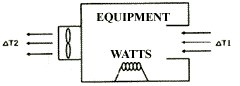
When air flows through a system, it encounters resistance due to obstructions from components inside the cabinet. This resistance limits the airflow and causes a pressure drop, referred to as static pressure (measured in inches of water).
To determine the cooling capacity of each slot, the system designer or manufacturer must consider both the fan's characteristic curve to identify maximum airflow and the system’s air resistance curve. The loss of air pressure due to resistance inside the cabinet is known as system resistance, and this loss varies with airflow.
The system characteristic curve is defined as:
ΔP = K × Q^n
Where:
For laminar (stratospheric) flow, n = 1, and for turbulent flow, n = 2.
The system operating point is defined by the intersection of the system impedance curve and the air flow characteristic curve. This point represents the optimal operating point for the fan in the given application.
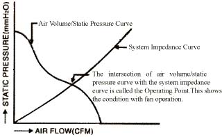
At the operating point, the slope change of the fan characteristic curve is minimized, while the rate of change of the system characteristic curve is at its lowest.
Additionally, the static efficiency of the fan—calculated as the air flow multiplied by static pressure, divided by power consumption—is also optimized.
Design Considerations:
Ensure the air flow path is as unobstructed as possible, with both the air inlet and outlet free from blockages to promote smooth airflow.
Direct the air flow through the system vertically to enhance smooth air movement and improve cooling efficiency.
If an air filter is required, take into account the additional resistance it adds to the airflow.
Examples of selecting the best fan for your application:
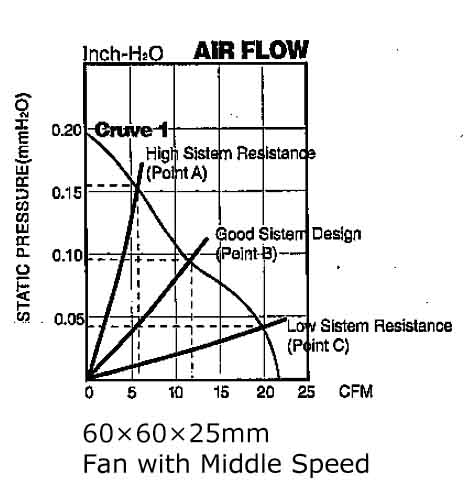
Example 1:
Figure #1 illustrates the air characteristic curve of a 60 × 60 × 25 mm DC cooling fan. This fan could operate at Point A or Point C, providing 6 CFM or 20 CFM, respectively, depending on whether the system's resistance causes a pressure drop of 0.16 Inch-H2O (at Point A) or 0.04 Inch-H2O (at Point C). If the system operates at Point B due to improvements, the fan could deliver 12 CFM at a pressure of only 0.09 Inch-H2O.
Example 2:
As depicted in Figure #2, Characteristic Curve 2 represents a fan with the same size and shape as Characteristic Curve 1, but operating at a lower speed. If the system demands 15 CFM at 0.05 Inch-H2O, the intersection of the static pressure and airflow curves should pass through point B. At this point, the fan delivers 18 CFM with zero static pressure, which is sufficient for cooling. Therefore, the optimal choice is to select a fan operating at a lower speed.
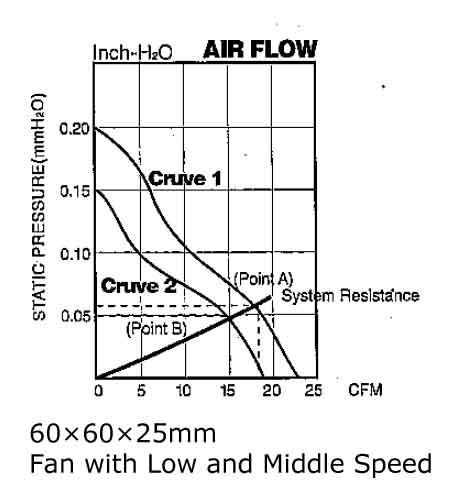
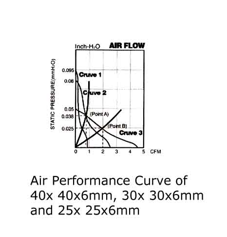
Figure 3 illustrates the air performance curves for the following medium-speed DC fans: 40 × 40 × 6mm (Curve 3), 30 × 30 × 6mm (Curve 2), and 25 × 25 × 6mm (Curve 1).
Case 1:
For a system with an impedance of 0.025 Inch-H2O and a required airflow of 2 CFM for cooling, the recommended fan is the 40 × 6mm DC fan (see point B).
Case 2:
If additional components are added to the system or there is a more compact physical reconfiguration, system impedance will increase. In this case, the system impedance rises to 0.038 Inch-H2O, with a required airflow of 0.85 CFM. Two fan options are available for selection: the 40 × 6mm and the 30 × 6mm fans (refer to Operating Point A). An alternative solution for cooling a high-impedance system is to use a Micro DC blower.
 Sales
Sales